What Are You Looking For?
During transformer maintenance, the on load tap changer (OLTC) must undergo disassembly, inspection, and reassembly. The overhaul includes the following critical tasks:
Inspect, maintain, and commission the OLTC core suspension system.
Clean, perform leak detection, and repair the OLTC oil chamber.
Inspect, clean, lubricate, and service the drive mechanism.
Verify and recalibrate the linkage between the tap changer and drive mechanism.
Inspect and maintain the oil reservoir cabinet and accessories.
Treat insulating oil in the oil reservoir and oil chamber (e.g., filtration, degassing).
Inspect, maintain, and calibrate the oil flow control relay (or gas relay), overpressure relay, and pressure relief device.
Test automatic control systems and electrical circuits.
Inspect seals across all components and address oil leaks.
Unscrew bolts securing the switch head cover. Remove the cover while protecting the sealing gasket.
Verify alignment between the switch drive shaft notch and triangular marker on the support plate.
Remove the position indicator plate and its lock plate.
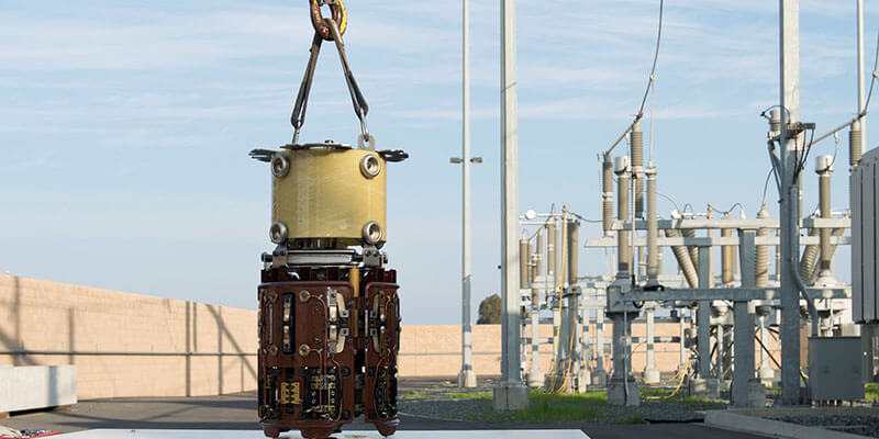
Detach nuts connecting the switch body to the support plate. Use a lifting sling to vertically extract the switch body and place it on a plastic-covered platform.
Remove the oil suction pipe. Clean the oil chamber thoroughly if contaminated.
Use a dedicated lifting plate to separate the intermediate flange from the support flange.
After lifting the upper oil tank, inspect:
Tightness of selector-to-switch copper rods.
Contact quality between tap leads and static contacts.
Horizontal tension on selector bakelite strips (must approach zero).
Proper alignment of moving contacts relative to static contacts (≥2mm from spherical section).
Measure transition resistor values using a bridge or multimeter. Ensure deviations from nameplate values remain within ±10%.

Reinstall the upper oil tank. Flush the diverter switch oil chamber with clean oil and reattach the oil suction pipe.
Lower the switch body vertically into the oil chamber, gently rotating the insulating shaft to engage couplings.
Reattach the position indicator plate and secure the shaft head lock.
Tighten switch head cover bolts to ensure a leak-free seal.
Install a bypass pipe between the oil return line and transformer tank for simultaneous vacuum oil filling.
Install worm/bevel gearboxes, horizontal/vertical shafts, and rain covers.
Manually operate the mechanism in both directions to verify symmetry (forward/reverse rotation difference ≤1 turn).
Perform electric operation tests to ensure tap position indicators align with the drive mechanism.
Set the tap position to the rated value.
Drain oil/air and remove the switch head cover.
Loosen the oil suction pipe elbow nut.
Detach the gear mechanism lock screw and note position markers.
Extract the oil suction pipe using a screwdriver to pry it upward.
Attach a lifting tool to the selector switch coupling. Rotate clockwise to position moving contacts between phases.
Carefully lift the switch body while maintaining clearance from equalizing rings and oil chamber walls.
Secure the oil chamber with M8 screws. Remove flange bolts and lift the chamber onto a support plate.
Clean and reinstall the chamber, ensuring:
Coaxial alignment between the selector switch and oil chamber.
Proper calibration of the gear mechanism.
Sealing gasket placement before head cover reinstallation.
Install bypass piping for simultaneous oil filling.
Verify transmission symmetry and perform trial operations.
Inspect for damage/deformation in switches, tap selectors, and conversion selectors.
Check insulation components for cracks, tracking, or moisture.
Verify tightness of all electrical connections. Measure contact resistance and pressure.
Confirm transition resistors are intact (no breaks/loosening) and within tolerance.
Ensure tap leads exert no tension on the OLTC.
Validate insulation distances between tap leads and adjacent components.