
Pad-Mounted Transformer Protection: Coordinating Fuses, Switches, and Arresters
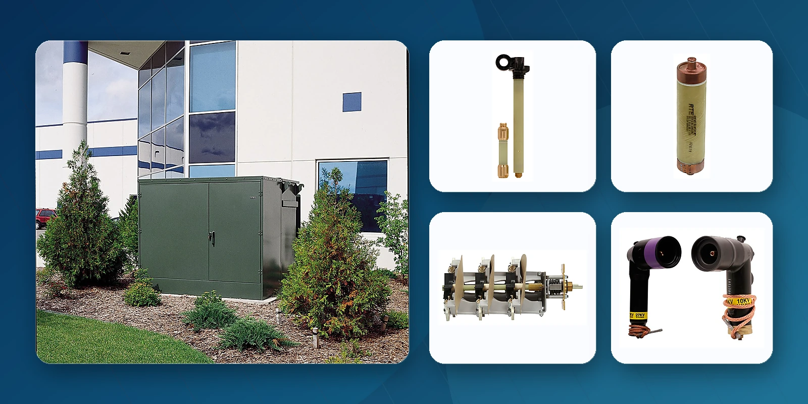
1. The Protection Trinity: Fuses, Switches, and Arresters
A pad-mounted transformer faces three distinct threat categories, each requiring a different protection approach:
| Threat | Protection Device | Operation | Key Cooper Models |
|---|---|---|---|
| Overcurrent / Fault | Bay-O-Net + ELSP two-fuse scheme | Clears persistent overcurrents and faults. Bay-O-Net handles routine events; ELSP clears catastrophic faults. | 4000353C12B (23kV, 40A Bay-O-Net) CBUC15150D100 (15.5kV, 150A ELSP) |
| Surge / Overvoltage | MOV distribution or elbow arrester | Clamps transient overvoltages from lightning and switching. Non-operating under normal voltage. | 3238018C15M (15kV MOV arrester) Elbow arrester (dead-front) |
| Isolation / Reconfiguration | Load break switch | Provides visible isolation for maintenance. Enables source transfer and loop reconfiguration. | LS2B338H3N2A (38kV, 300A 2-position) LS4RH3T16B (24kV, 400A, 4-position) |
The critical insight is that these devices must not only protect against their respective threats — they must coordinate so that the operation of one device does not trigger false operation of another.
2. Representative System Configuration: 15.5kV, 3-Phase Pad-Mounted Transformer
Let's walk through a complete protection system for a common North American pad-mounted transformer configuration. The model numbers below are representative references and must be verified for the actual application.
Overcurrent Protection Layer
- Primary (routine) protection: Bay-O-Net Current Sensing fuse link, 4000353C12B — 40A, 23kV rated. This fuse link clears secondary faults, moderate overloads, and through-faults. Field replaceable via hotstick without entering the tank.
- Backup (catastrophic) protection: ELSP current-limiting fuse, CBUC15150D100 — 15.5kV, 150A. Connected in series with the Bay-O-Net. Only operates on high-magnitude internal faults exceeding the Bay-O-Net's interrupting capability.
- Fuse assembly: Sidewall-mounted Bay-O-Net assembly with Flapper valve — minimizes oil spillage during fuse changes. Part number: 4038380B03M (38kV Flapper Bay-O-Net assembly, silver-plated).
- High ampere option: For larger kVA ratings, substitute 4000353C17B (140A, 23kV) Bay-O-Net link and CBUC15180D100 (15.5kV, 180A) ELSP fuse.
Switching Layer
- Primary isolation: LS2B612H3N1A — 12/15kV, 630A, 2-position load break switch. Provides ON/OFF isolation of the transformer from the primary feed.
- Source transfer option: LS4B615H3T16B — 15.5kV, 630A, T-blade 4-position sectionalizing switch. For loop feed applications with alternate source capability. Make-before-break option available: 2290318D04CH.
Surge Protection Layer
- Externally mounted: 3238018C15M — 15kV distribution-class MOV arrester. Installed at the transformer primary terminals.
- Dead-front option: Elbow arrester — plugs directly into 200A loadbreak bushing insert for installations where external arrester mounting is impractical.
- Under-oil option: Under-oil high-voltage MOV arrester — installed inside the transformer tank near the primary winding for the ultimate in surge protection proximity.
Bushing & Connection Layer
- Bushing well: BW150R — 35kV, 150/200A tri-clamp bushing well with fixed or removable stud.
- Loadbreak insert: LB235B150GCX — 35kV, 150/200A loadbreak bushing insert.
- Elbow connector: LE215A00TC — 15kV, 200A loadbreak elbow connector with optional integral jacket seal.
Voltage Adjustment Layer
- Tap changer: CA800003EN — 100A externally operated tap-changer switch, 1-phase configuration.
- Switch cap: 2237947A10H — tap changer switch cap with wrench operation.
- Cap wrench: 2237471C16M — dedicated tap changer operation tool.
3. System Coordination Principles
Time-Current Coordination
The Bay-O-Net fuse and ELSP backup fuse must coordinate on the time-current curve (TCC):
- The Bay-O-Net link should clear all currents up to its maximum interrupting rating (approximately 3,000-3,500A asymmetrical)
- The ELSP fuse's minimum interrupting rating must be above the Bay-O-Net's maximum interrupting rating
- Below the minimum interrupting current, the ELSP fuse must not operate — even if it takes seconds for the Bay-O-Net to clear
- Above the crossover point, the ELSP fuse clears the fault with full current-limiting action in less than half a cycle
Arrester-Fuse Coordination
The surge arrester's operation during a lightning strike must not cause the Bay-O-Net fuse to operate:
- Lightning surge duration: microseconds to milliseconds
- Bay-O-Net fuse minimum melting time: hundreds of milliseconds to seconds
- The arrester diverts surge energy to ground within microseconds, before the fuse element can heat significantly
- However, if the arrester fails short-circuit (rare but possible), the Bay-O-Net must clear the resulting fault current
4. Additional System Components
Visible Break Window
A visible break window provides positive visual confirmation that the switch contacts are open — a critical safety feature for lockout/tagout procedures. The window is integrated into the transformer tank above the switch mechanism.
Fuse/Switch Interlock
Mechanical interlock prevents operation of the load break switch while the Bay-O-Net fuse holder is removed, or vice versa. This prevents dangerous configurations where personnel might assume isolation that doesn't exist.
VFI (Vacuum Fault Interrupter)
For applications requiring electronic trip control and reclosing capability, the VFI integrates vacuum interrupter technology with microprocessor-based protection. VFI-equipped transformers offer advanced protection features including phase and ground overcurrent, sensitive earth fault detection, and event recording.
5. Selection Checklist: Building Your Protection System
- Determine system parameters: Primary voltage, BIL, available fault current, system grounding type
- Select Bay-O-Net fuse link: Choose link type (Current Sensing, Dual Sensing, Dual Element, or High Ampere Overload) and ampere rating based on transformer kVA and loading profile
- Evaluate need for ELSP backup: If available fault current exceeds Bay-O-Net interrupting rating, select coordinated ELSP fuse
- Choose switch type: 2-position for simple isolation, 4-position for loop feed/source transfer, add make-before-break if zero-interruption transfer is needed
- Specify arrester: Match MCOV to system voltage, select elbow or external mounting based on transformer construction
- Complete the connection system: Bushings, bushing wells, separable connectors compatible with selected voltage class and current rating
- Verify coordination: Review TCC curves to confirm all devices coordinate across the full fault current spectrum
Manufacturer Resources
Use the latest manufacturer literature for final ratings, ordering codes, installation, and safety requirements.
Frequently Asked Questions
What devices are normally included in pad-mounted transformer protection?
Depending on the design, the package may include a primary expulsion fuse, a backup current-limiting fuse, a loadbreak or sectionalizing switch, surge arresters, bushings, and separable connectors.
Why must Bay-O-Net and ELSP fuses be coordinated?
The operating regions must overlap correctly: the low-current device should clear within its capability, while the backup fuse should interrupt high-current faults without operating below its minimum interrupting range.
Can the example part numbers be copied directly into another project?
No. They are reference examples only. The final selection must be checked against the actual voltage, kVA, fault current, fluid, BIL, interface, and current Eaton data.
Building a Transformer Protection System?
Jiuyingtech provides complete Eaton Cooper protection packages. Send us your transformer specs and we'll recommend the optimal combination of fuses, switches, and arresters with full coordination analysis.