What Are You Looking For?
In a 35kV high-voltage distribution network, if the transformers and switchgear are the "heart" of the system, then the Apparatus Bushing is the "throat." It is a critical component that not only facilitates the transmission of high current but also provides essential insulation and sealing in high-voltage environments.
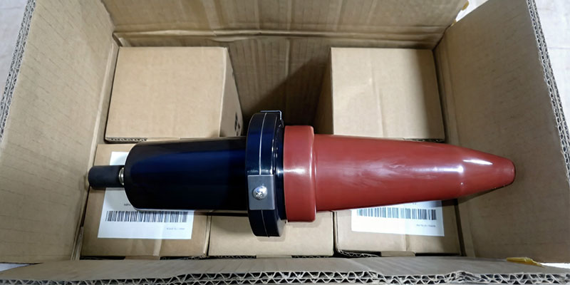
Today, we will explore the core technology behind the Eaton Cooper Power series 600A 35kV Class Deadbreak Bushing and why it is a staple in modern infrastructure.
In power engineering, connectors are generally classified as either "Loadbreak" or "Deadbreak."
The Definition: A Deadbreak bushing is designed to be operated (connected or disconnected) only when the system is de-energized (no load).
Why 600A?: While 200A systems often use Loadbreak connectors for quick switching, 600A systems prioritize physical stability and high current capacity. The Deadbreak design utilizes a bolted connection, providing a robust interface that can handle significant electrical and mechanical stress.
Standardization: These bushings meet the full requirements of IEEE Std 386™-2006. This ensures that any 600A separable connector (such as the BOL-T™ or T-OP™ II) manufactured to this standard will be perfectly compatible, regardless of the brand.
The bushings are molded from high-performance Epoxy Resin. This material is chosen for several critical reasons:
Dielectric Strength: It provides a BIL (Basic Insulation Level) rating of 150kV, protecting the system against lightning strikes and voltage surges.
Chemical Compatibility: It is designed for sidewall mounting in apparatus filled with mineral transformer oil or bio-based fluids like Envirotemp™ FR3™. It resists degradation even after decades of immersion in these fluids.
Stress Management: Every bushing includes an internal ground screen. When connected to the system ground via clips and clamps, this screen helps distribute electrical stress evenly, preventing insulation failure.
A bushing's reliability is proven by its production test data. According to the technical documentation:
AC 60 Hz 1-Minute Withstand: 50kV. This ensures the unit can handle extreme temporary overvoltages without flashover.
Minimum Partial Discharge (PD) Level: 26kV. Partial discharge is the silent killer of insulation. By maintaining a high PD threshold, these bushings ensure an exceptionally long service life with minimal internal erosion.
Current Flexibility: While the standard rating is 600A (continuous), using an all-copper threaded stud can increase the continuous current rating to 900A, allowing for future-proof system expansion.
A bushing failure often leads to catastrophic results, such as transformer oil leaks or fires. This 35kV bushing utilizes a specialized external clamping system and high-quality Buna-N gaskets to create a leak-proof seal. Whether it is installed in a compact pad-mounted transformer or a high-voltage switchgear gallery, it is built to withstand temperatures ranging from -40°C to 65°C.
Though it may look like a simple piece of molded plastic, the 35kV 600A Deadbreak Bushing is a masterclass in materials science and high-voltage engineering. Selecting a component that meets IEEE standards and offers high-current flexibility is the first step toward building a resilient and maintenance-free power grid.